Undercuts are incorporated to deal with complex designs so that the part can be removed from the mold without causing any damage.
Undercut designs are used to create threaded parts, such as screw-on bottle caps, and snap-on products such as lipstick containers. Typically, undercut features are incorporated to support complicated designs but they also increase the overall complexity of the design thereby increasing the associated costs. Thus, undercuts are included in the design only when required and when it is considered necessary to do so. In this article, we discuss what are injection molding undercuts, various processes used to create undercuts in molding, and their applications in detail.
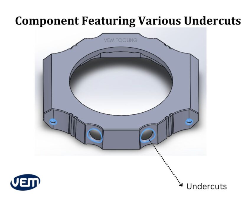
Undercuts enable manufacturers to achieve complex plastic part designs for the injection molding process.
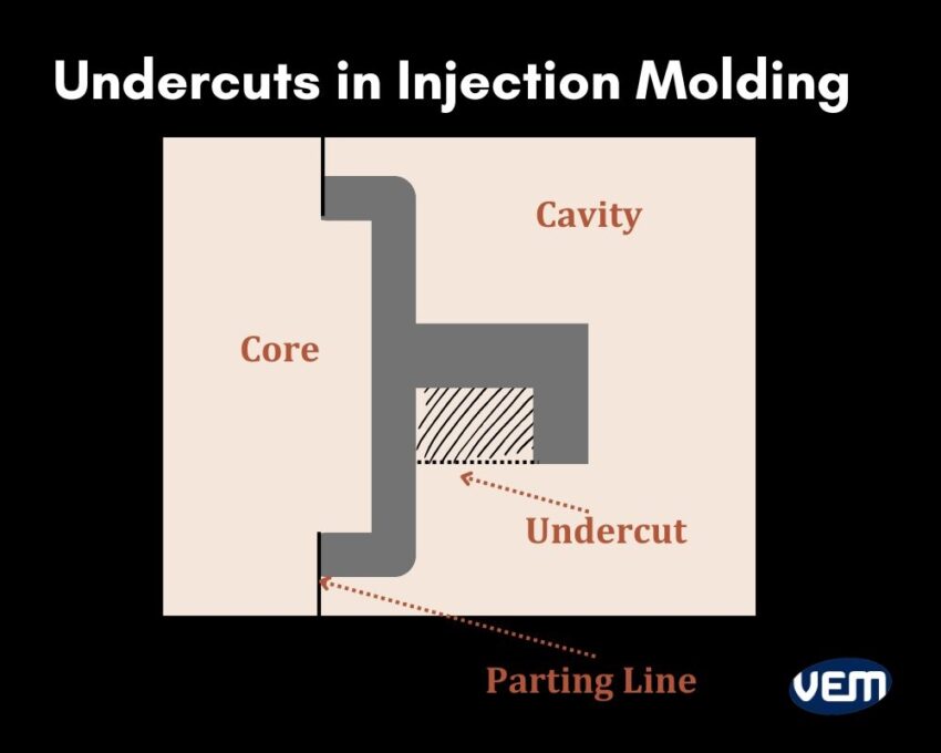
An undercut in injection molding is a type of depression or protrusion that prevents it from being withdrawn from a one-piece mold. Undercuts prevent the part from being ejected directly from the mold. It is a feature in which the cavity and core cannot be captured alone and are die-locked which further prevents the part from being ejected from the cavity.
Undercuts can either be internal or external. External undercuts are located on the outside of the component whereas interior undercuts are located on the inside.
Undercuts in injection molding are essential for creating hooks, grooves, and other elements that can directly impact the part’s functionality.
Though undercuts increase complexity and cost, they also support functionality. Undercuts are applied to create various part features that range from product assembly to fluid flow. They are often used as threads for plastic fasteners, interlocks for clam-shell housings, and holes for wire or cable pass-throughs.
Undercuts can also be incorporated for coring which is the process of eliminating plastic material from thicker sections of the mold. This minimizes the risk of injection molding defects such as sink marks and warping by avoiding longer cooling times. Coring creates ribs and distinct walls to support parts within a larger assembly. It also reduces material usage and weight.
Undercuts in injection molding are typically avoided however; there are some case scenarios, where undercuts are necessarily incorporated in the mold design. Let’s understand these scenarios further:
The undercut injection molding process enables manufacturers to create custom inserts that can fit into larger parts. These types of inserts are apt for medical devices as they need to include an exact fit. Undercut inserts can also be included as an alternative to screws or rivets for attaching two pieces.
Undercut injection molding helps to create side holes that are otherwise difficult to create via traditional manufacturing practices. Side holes enable manufacturers to include access points such as buttons and ports in the housing unit.
Side holes are incorporated for mounting components or attaching them to other pieces of equipment. They can also be incorporated to add a design element or vent heat inside the part.
Vertical threads are commonly found on multiple connectors, hoses, bolts, and screws to create secure connections that can bear light stresses and loads. They can also be used as an assembly part to thread multiple parts together as one unit.
Barb connectors are a type of component that is commonly used to control airflow. In the case of barb fittings, the male part is undercut to form a lip to hold the female part of the barb fitting.
Undercuts in injection molding are often used to create interlocking features. These features allow for clamshell or housing designs to assemble easily and quickly.
Creating undercuts in injection molding is a complex process that requires extensive technical expertise, a high competence level, and mold alterations. It is also dependent upon various factors such as part geometry, production volume, material, and the required dimensional accuracy.
Let’s understand some of the ways that you can create successful undercuts or deal with undercuts in molded parts:
The very first way to deal with undercuts is to redesign the part itself thus, it is recommended to review the part design and identify the various areas with undercuts.
If it’s possible, the part geometry should be modified to minimize or eliminate undercuts in the most efficient way possible. You can redesign the part by changing the parting lines or the draft angles. You can also split the part into various pieces to allow for easy ejection.
The parting line is the intersection area between both molds. It is where the two halves of the mold separate to release the part. The placement of the parting line depends upon an array of factors such as geometry, material properties, flow properties, and other features of the part.
One of the simplest ways to work with undercuts is by moving the mold’s parting line to overlap an undercut. Thus, when the feature is split in half by the parting line, the component can be released from the mold without needing an undercut.
You can consider moving the mold’s parting line so that it intersects with the undercut and this is sometimes the easiest part-release solution, however; the parts will still need enough draft for easy ejection. The parting line can also be created in a zigzag pattern which can align with various features, thus, eliminating the need for undercuts.
You can think of using a split mold design. In this case, the mold is split into two or more separate pieces. These separate pieces release the part with undercuts and the split line leaves a mark on the part.
You can choose to incorporate side cores and collapsible cores to deal with undercuts in injection molding. Let’s understand these further:
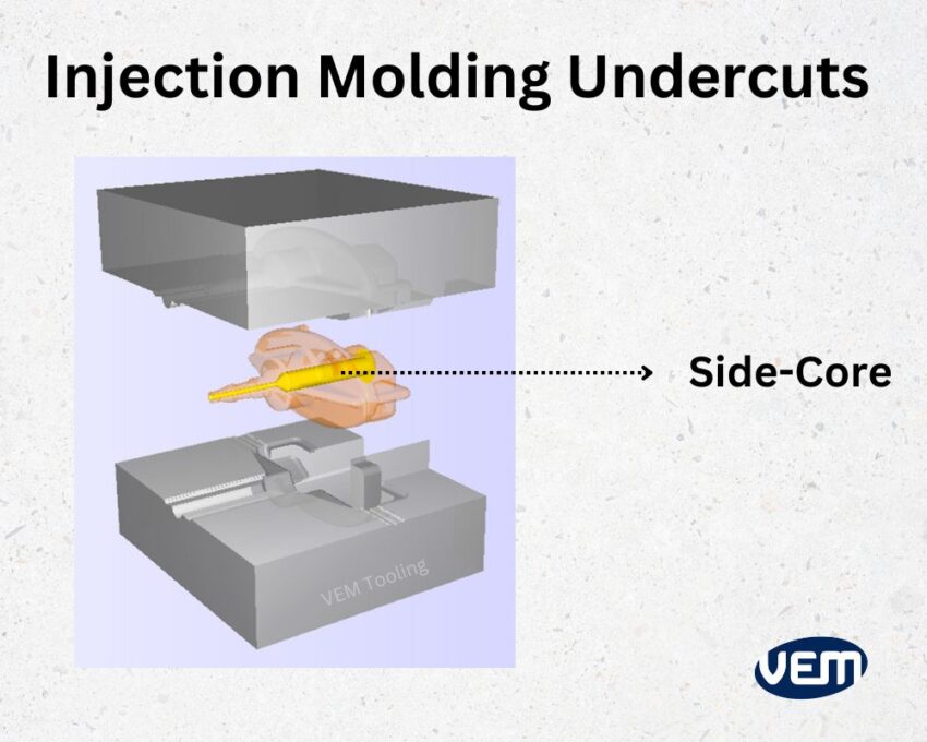
When an undercut is necessary, a side-action feature can maintain the part functionality. Side-action features are typically employed with cylindrical components, where the mold separates horizontally along the part.
A side-action insert slides out of the part during ejection. When the molten resin is injected, the volume cannot be filled in due to the insert thus, when the insert slides out, an undercut is left behind. There are various limitations to this design.
Firstly, for the side action core to be effective, it needs to be perpendicular, and to ensure this particular perpendicular motion, the mechanism has to be designed accordingly, which further adds complexity to the mold design.
Secondly, the side action core works best with rigid materials and materials that don’t stick to the mold easily such as nylon, Acetal, and PC.
Bump-offs are apt for flexible and elastic materials. They enable just enough deformation of the part so that it can exit the mold, without experiencing wear.
You should note that the leading edge of the undercut should have a smooth radius so that the part releases easily.
The process works with the addition of a single insert and when the injection molding process is complete, the insert is removed, leaving a space behind to eject the part efficiently. Since there is a hollow space inside the mold, the part can deform slightly, which enables it to be ejected while having an undercut.
Several factors need to be considered for bump-offs as there are various restrictions on using bump-offs for undercut injection molding. These restrictions are listed below:
This is a manual technique performed by the technicians and is typically opted for when no other method works. These inserts are placed into a mold manually and they are placed before the cavity is filled. Hand-loaded inserts are employed when it is necessary to include an undercut for challenging features such as a lip with a sharp angle or when an additional feature such as a hole needs to be placed in a difficult position.
Hand-loaded inserts are metal pieces that are placed in the mold manually. The metal pieces create a cavity as they prevent the resin plastic from flowing into the spaces they occupy. The operator can freely remove the metal piece once the cycle is over and reuse it for the next batch.
The location and the number of metal pieces depend entirely upon the undercuts that the machined piece requires.
There are some concerns and limitations with using hand-loaded inserts for undercut injection molding such as extended lead times. Since this is a manual process, it would simply take more time which increases the lead time. The next concern is that since higher temperatures are involved, even though workers use PPE for safety, there is always a chance of burning yourself.
Shutoffs are typically employed, when a feature, such as a hook that is situated at the outside of the mold cannot be easily created by any other method. Shutoffs are a type of temporary obstruction that includes various components such as hooks and clips. These components snap-fit to prevent the flow in various design regions. Shutoffs can eliminate side action cores or hand inserts thereby, eliminating any type of increments in cost or production time.
There are, however, certain design requirements that need to be considered such as the sliding shutoffs must be exceedingly tight to avoid substantial friction when you open and shut the tool. In addition, you should note to draft each of the surfaces by about three degrees to prevent any mold damage. It’s imperative as full metal-to-metal contact won’t occur until and unless the mold is completely closed and a mechanical seal is formed.
Undercuts in injection molding are applied to various industries and sectors. Let’s understand its applications further:
Consumer electronics largely rely on plastic housing since they are insulated, durable, and economical. The plastic housing needs to have various undercuts to add buttons, switches, and various other elements for the users. These undercuts allow access to the internal housing.
Undercuts in consumer electronics are also used to create cavities for electronic components. For instance: such as mobile phones and laptops.
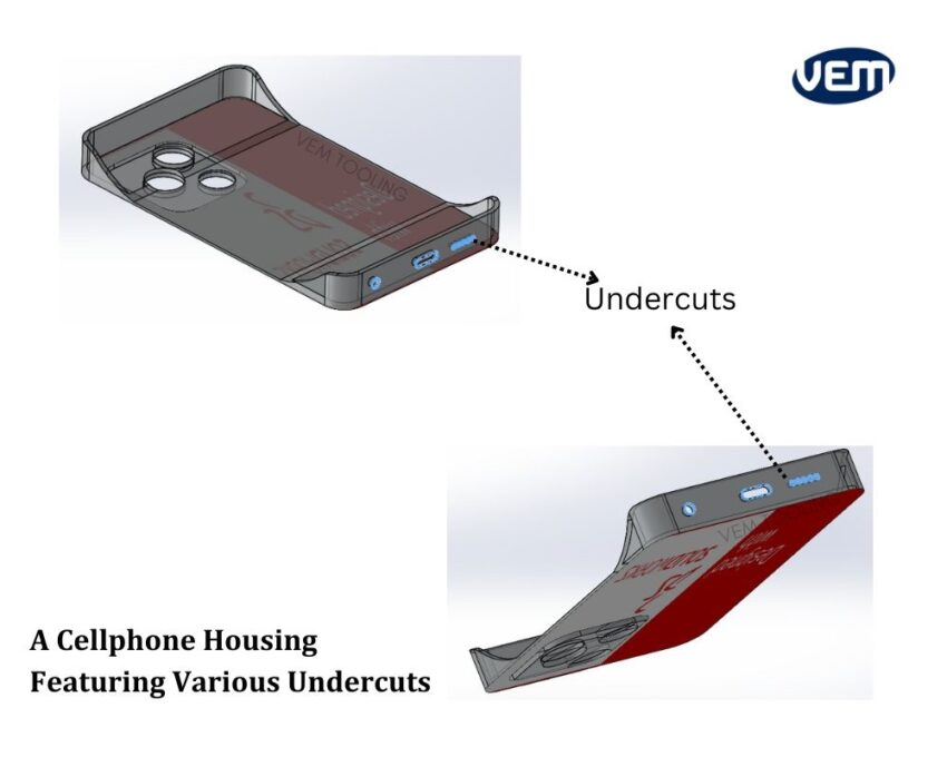
The following image showcases a cell phone housing with various undercuts. These features are functional and include buttons, hinges, and portholes. You should note that each undercut that is included here adds to the complexity of the mold.
There are various challenges with undercuts in injection molding and they can arise due to the design, material choice, and aesthetic requirements of the machined part.
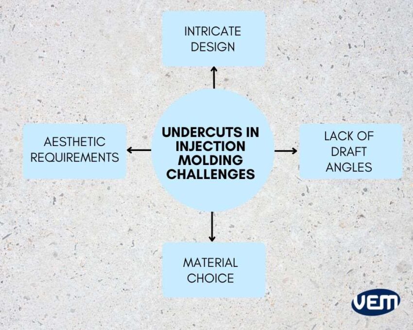
If the design is more intricate, then there will be more complications. You should note to adjust the draft angles, cavity angles, and other complex angles to reduce any ejection process difficulties. Thus, the setup must be as simplified as possible.
One of the biggest challenges with molded parts is a lack of draft angles. You should note that it is difficult to remove the non-drafted areas.
Demolding parts with insufficient drafts create difficulty in removing the side action manually. To ensure great performance, it’s best to control draft angles.
The next challenge is the material choice and the general rule of thumb is that if the material is extremely rigid, then there will be more issues in the extraction process.
The overall flexibility and material elasticity are crucial factors in implementing the aptest solution to optimize undercuts in injection molding.
The harder the material is, the more difficult it is to extract it thus, it is recommended to use as much draft as possible when employing tougher materials.
The next factors that are often challenging are the aesthetic requirements of the project. If you don’t want a visible parting line on an injection molded part, then the design solution will pose some limitations which leads to further complications that need to be dealt with.
Undercut in injection molding supports various design solutions but it also increases complexity and adds cost. The right manufacturing partner can help you navigate the best solution for your project.
If your part design includes essential undercuts, VEM Tooling can guide you with the best undercut practices. If an undercut is non-essential, we can help you with alternative design solutions. VEM-Tooling has vast experience to help you manufacture parts.