Injection molding is a popular manufacturing technique for creating plastic parts that are extremely precise. When a design is created, there are typically variations between the design and the finished plastic part. The range of deviation of the variations that still allows the part to function as designed and required is referred to as tolerance.
Tolerance in injection molding is especially necessary when multiple components of a part need to fit together in an assembly. You should note that when critical tolerances aren’t met, the multiple components of the part won’t fit correctly, leading to a failed assembly and an increase in production cost. Thus, understanding injection molding tolerances is a necessary aspect of the manufacturing process. In this article, we discuss in detail the various factors that affect injection molding tolerances and how to further optimize them.
Injection molding tolerances are acceptable variations and permissible limits within which the dimensions of a molded part can vary from its design while maintaining its functionality. It greatly varies by the type of material that’s used and the overall size of the part.
These tolerances are crucial in injection molding, as even slight deviations can cause aesthetic defects, assembly errors, or functional concerns. For instance, if the holes in two parts meant to be bolted together are not accurately sized due to incorrect tolerances, it could lead to assembly errors and function loss.
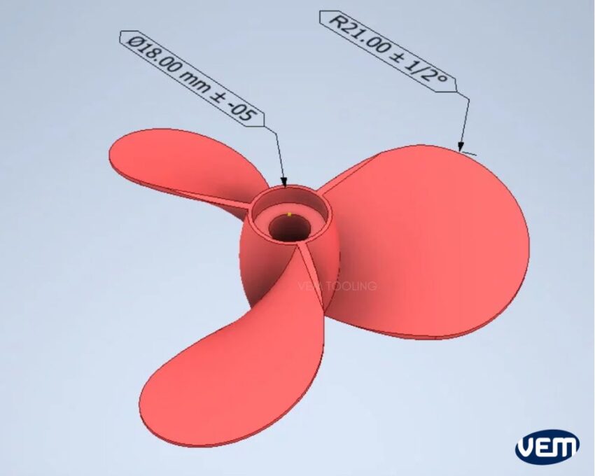
Tolerance in Injection molding is expressed as plus or minus (±) values from the expected dimension. Tolerance is added to the CAD files by the designers to indicate the allowed amount of variation.
Parts with tighter tolerances are typically more expensive as they have stricter tooling and processing requirements. In such cases, mold quality, consistent cooling temperatures, and proper cavity fill rates are critical aspects.
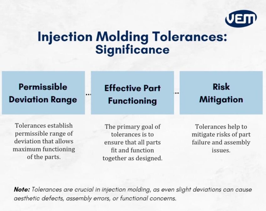
In any process, a degree of variation is inevitable. Tolerance in injection molding determines the permissible range of deviation that allows maximum functioning of the parts. If the tolerance is not in control, the assembling will fail. Thus, it is critical to determine an acceptable deviation range for the parts to function effectively after assembly.
Injection molding tolerances play an effective role in the functioning of parts. The primary goal of tolerances is to ensure that all parts fit and function together as designed, even when there are variations in the manufacturing. Tolerances primarily, account for these variations.
Determining the acceptable range of deviation ensures optimal functioning of the product, thereby enabling you to prepare for worst-case scenarios. Tolerances help to mitigate risks of part failure and assembly issues.
Let’s understand some of the most common types of injection molding tolerances for specific part features:
This type of tolerance refers to the overall part size. You should note that injection molding tolerances are always listed for specific size ranges.
Each thermoplastic has a different tolerance range and if the part size is increased above expectations, then the shrinkage will be larger during the cooling.
This type of tolerance refers to the general warping of straight and flat areas of the part. Warping in plastic parts occurs primarily due to different shrinkage rates in the mold across the mold flow. It can also occur due to varying wall thickness thus, tweaking the mold design can avoid the occurrence of warping to an extent. In addition, various features of the mold design such as better gate location and uniform cooling can also reduce the occurrence of warpage in plastic parts.
Concentricity or ovality involves determining the wall thickness i.e. the difference between the inside and outside diameter. In this case, a large cylindrical part can shrink unevenly if the wall thickness is thin, making the plastic part lose its circularity.
Blind holes are drilled into a workpiece with the help of an insert core without breaking through. They require a cantilever-type feature in the mold. If the molten resin is injected at a very high pressure, then the pin inserts can deflect. You should note that if the hole is deeper, then the likelihood of deflection is higher.
Depending upon the amount of precision required, injection molding tolerances can be divided into commercial and fine tolerances. Let’s understand the difference between the two types of tolerances:
Precision or Fine Tolerances: These types of tolerance incorporate more expensive molds and subsequently produce high-quality parts that have a tighter tolerance band.
Let’s understand the various types of inspection techniques that can be implemented to verify injection molding tolerances:
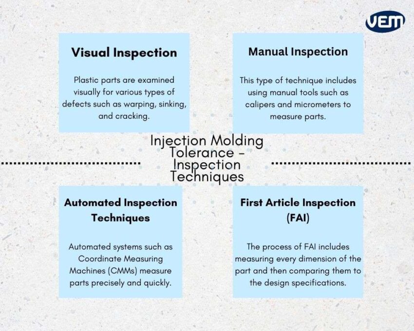
This is one of the simplest types of inspection techniques. In this technique, the plastic parts are examined visually for various types of defects such as warping, sinking, and cracking.
This inspection technique is particularly used for examining simple plastic parts that have fewer critical dimensions. A manual technique uses tools such as calipers and micrometers to measure parts manually.
Automated inspection techniques are particularly used for complex parts that have various critical dimensions to be measured. Automated systems such as Coordinate Measuring Machines (CMMs) and Vision Systems measure parts precisely and quickly. They are also able to deliver accurate reports on the dimensions and tolerances of the part.
FAI is a comprehensive inspection that is performed on the T1 sample or the first sample that is manufactured. The primary goal of FAI is to ensure that the required tolerances have been achieved.
The process of FAI includes measuring every dimension of the part and then comparing them to the design specifications.
Various factors influence the injection molding tolerances. Let’s understand these factors further:
Tooling is a crucial component of the manufacturing process and it plays a significant role in manufacturing high-quality parts.
When the molds are out of tolerance, the manufactured parts will also be beyond the tolerance levels. Achievable tolerances are impacted by the injection mold design and the number of cavities.
Injection molds must be able to deliver consistent and reliable results to maintain the required tolerances throughout the heating and cooling phases.
Typically, molds are machined to tolerances of ±0.05 in / ±0.127 mm. Tighter tolerances may require molds machined to ±0.002 in / ±0.0508 mm, and if extremely tight tolerances are expected such as for medical parts, then molds may need to be machined to ±0.001 in / ±0.0254 mm.
It is imperative to place cooling channels to include additional cooling for multi-cavity molds. You should note that when mold cavities are made from steel, the baseline for shrinkage calculations is more stable.
The recommended guideline for the base of a boss is 0.25 to 0.5 times the nominal wall thickness. If the radius at the screw boss’s base exceeds a maximum value, then thick sections can occur. In addition, a fillet of a minimum radius should also be incorporated at the tip of a boss to reduce further stress.
T1 tests or the first part samples demonstrate the mold’s ability to manufacture end-use parts. It enables the design engineers to validate the dimensions.
Typically, T1 samples can be manufactured and delivered within 14 days. These samples can be reviewed and upon approval, the mass-manufacturing can begin. If the T1 test sample is not as per the dimensions, then the design can be further tweaked to achieve the required injection molding tolerances.
Shrinkage is a key factor that affects the final dimensions of a part, and hence, the tolerances.
Shrinking directly affects injection molding tolerances, as parts typically shrink upon cooling and thus, it needs to be compensated for dimensional changes. This particularly, means that the part must be designed for its nominal dimensions and then additionally scaled up for expected shrinkage.
Part shrinkage is determined through ASTM D955, a standard test method that measures the thermoplastic shrinkage rate from mold dimensions. This test is intended to measure the shrinkage of thermoplastics from the mold cavity to the molded dimensions when they undergo molding.
In this test method, a sample is injection molded and then cooled after which, the part shrinkage rate is calculated. The equation to calculate the shrinkage rate is as follows:
Shrinkage Rate = 100 % (Lc – Lp) / Lp
This equation describes the linear shrinkage of materials and the calculated value reflects the decreased shrinkage in the melt flow direction. This particular method includes shrinkage measurements at 24 and 48 hours.
Let’s understand the typical shrinkage range (percentage) of some injection molding resins. We have enlisted some of the popular injection molding materials with their general range of shrinkage rates below:
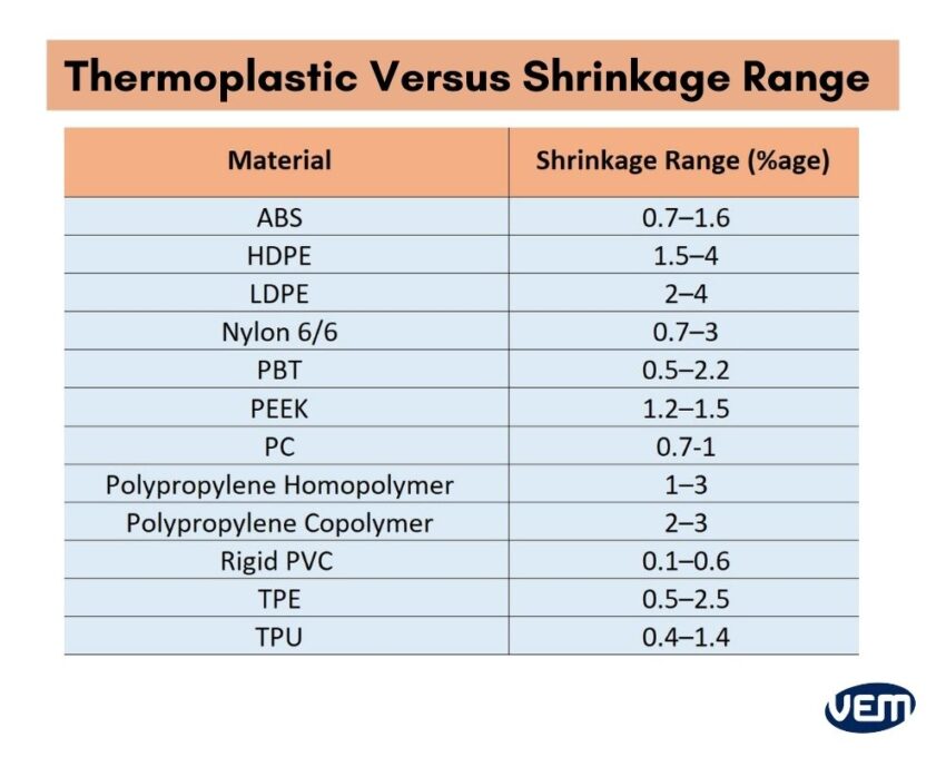
You should also note that semi-crystalline resins have higher shrinkage rates than amorphous resins.
The part design has a significant impact on the tolerances. Part design includes the geometry, size, and wall thickness, which can significantly influence the tolerances. You should note that larger parts and thick-walled designs are more challenging to maintain tight tolerances.
In addition, the part complexity also affects the material flow and tooling design as it’s more challenging here, to fill the mold quickly and maintain the right tooling temperature.
Since thermoplastics have a high thermal expansion coefficient, temperature variations can change their dimensions significantly. This directly impacts the ability to hold tight tolerances, especially in environments of extreme temperature changes.
Injection molding tolerances can be optimized by selecting the right injection molding materials, and tweaking the injection mold design or process controls. Let’s understand these aspects further:
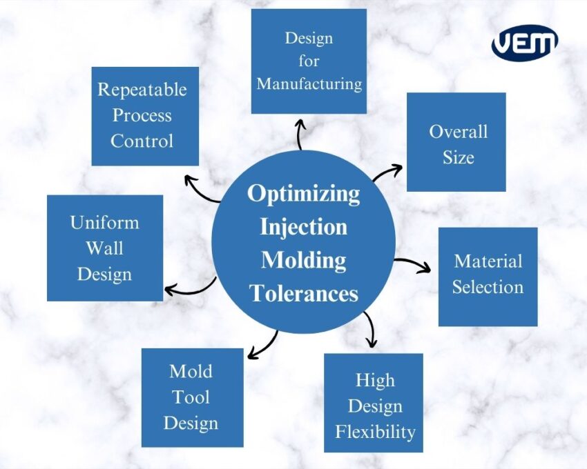
It is imperative to adhere to the principles of Design for Manufacturing (DfM). The primary goal of DfM is to facilitate an efficient and cost-effective production run while avoiding various types of issues such as warping, shrinking, and misalignment during molding.
Following standard DfM principles ensures that the defined tolerance parameters are met. A good DfM strategy helps to achieve tighter tolerances by limiting the occurrence of errors.
The overall part size has a significant impact on the injection molding tolerances such that the larger the part size, the harder it will be to hold tighter tolerances.
Large parts are more prone to distortions and injection molding defects such as warping and shrinking, thus, affecting the tolerances. It is hence, critical to consider the size of the part during the design phase.
Thermoplastics can impact uniform shrinkage significantly. It is imperative to select the correct resin as they can vary greatly in terms of physical and chemical characteristics, melt flows, and cooling rates.
You should note that every resin shrinks upon cooling and thus, shrink rate is a crucial characteristic to be considered when selecting the material. Every resin will have a different shrink rate and this aspect needs to be factored into the material selection and mold design process. You should note that resins from different batches or suppliers can also minutely differ in their shrink rates.
Along with the type of material, the shrinkage rate depends upon various factors such as wall thickness, temperature, and parts thus, you also need to consider the design of the part and the tool to achieve the correct tolerances.
When selecting a material, you must consider the following factors:
The next way to optimize injection molding tolerances is to maintain repeatable process controls. Process controls calibrate common variables that can affect part quality. These variables are integral to every manufacturing process.
There are various types of process controls such as temperature, pressure, and holding time and these process controls help to calibrate the variables that directly or indirectly affect the part quality.
Maintaining and executing process controls ensures repeatability and a predictable shrinkage rate. One of the ways to implement process controls is to embed temperature and pressure sensors in the mold. These sensors help to measure the mold environment and provide real-time feedback. This helps to execute process controls.
When the wall sizes of the parts aren’t uniform, the walls shrink at different rates. A uniform wall thickness helps to achieve a stable shrink rate which in turn reduces the occurrence of warping, sinking, and cracking.
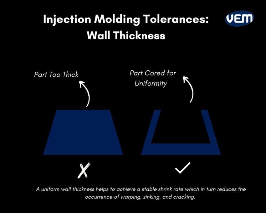
The thickness of part walls is one of the biggest contributors to ensuring dimensional stability, which is critical to staying within tighter tolerance ranges.
You should note that thick areas tend to sink more as they take longer to cool than the thinner areas which often leads to imperfections on the exterior as the molten resin shrinks inwards. The best way to avoid these defects is by ensuring that the wall thickness is consistent throughout the part. In addition, you can incorporate ribs for strengthening walls and radii on inside corners to reduce the occurrence of warping.
The design of the mold tool is crucial in attaining the required tolerances. Let’s understand how mold tool design can help optimize injection molding tolerances:
Cooling in injection molding is a crucial step as it determines the part quality. As noted above, the cooling of the part must be uniform. If the cooling isn’t uniform, it can lead to various types of defects which can affect the appearance, tolerance, and functioning of the part. To achieve efficient and uniform tool cooling, mold designers must consider placing cooling channels at strategic points in the mold. In addition, injection pressure, and fill time must be monitored consistently.
The gate is the point at which the injection molding materials enter the mold. If the gate is not located at the correct location, it can lead to an uneven fill rate which can lead to warping and shrinkage. Thus, it is an important aspect to be considered. The following thumb rules can be considered to minimize the occurrence of defects in injection molding:
Draft angles are a crucial aspect of the injection molding design. They facilitate easy removal of a part upon cooling from an injection mold thus, helping to reduce the damage that may be caused due to friction thereby, ensuring a smooth finish. There is no standard injection molding tolerance rule when incorporating a draft angle into the product design however, in most cases a draft angle of 10 to 20 degrees is suitable.
Bosses are integral as fastening components to the product design during part assembling. There are various considerations when it comes to designing and implementing a boss in your design. One of the guidelines is to avoid the incorporation of thick bosses as they are prone to creating voids and sink marks. You can read more about screw bosses in detail here.
An ejector pin is a type of feature in an injection mold that ejects the part from the mold. If the ejector pin is not in the right position, then it can cause indentations on the part. An ejector pin can also cause ruptures if the material isn’t rigid, thereby, leading to several aesthetic defects.
Tolerances in injection molding ensure that the parts are functional as per the intended design, fit together properly in an assembly, and meet the required specifications.
VEM-Tooling has a vast experience of over 20 years in manufacturing high-quality plastic parts. At VEM-Tooling, we have an experienced team of engineers who can help you with the necessary solutions to actualize your goals.