Injection molding is one of the most efficient manufacturing processes for creating high-quality plastic parts but it is a complex process that includes molds, injection molding machines, and plastic engineering materials. This complexity introduces various challenges and limitations which give rise to the formation of defects!
Defects impact the quality, functionality, and aesthetics of the part which ultimately renders the parts defective. These defects can be prevented with key adjustments to the injection molding process. In the previous articles, we discussed plastic warpage, weld lines, and sink marks, and in this article, we explore one of the most common types of defects that are known as ‘Flow Marks’. If flow marks are detected early, it can prevent various issues and costs.
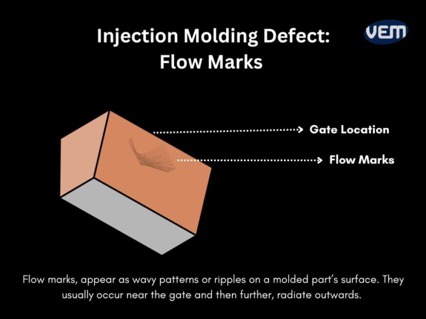
Flow marks, also referred to as flow lines, appear as wavy patterns or ripples on a molded part’s surface. Flow marks commonly occur as lines or circles and they indicate an uneven material flow.
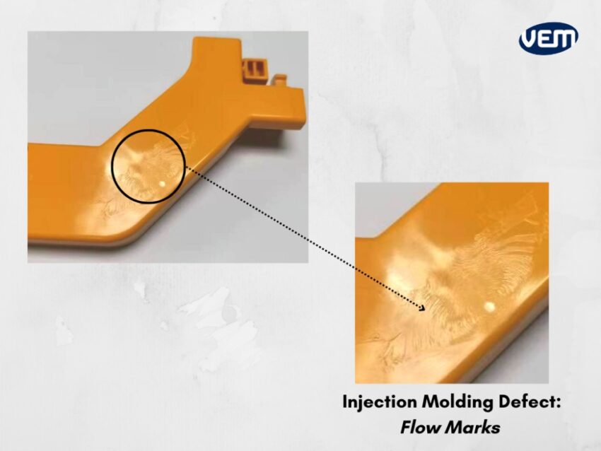
They are not necessarily detrimental to the structural integrity but they can impact to reduce the aesthetic qualities of the part. These are the types of defects that can affect the external appearance of the part and depending upon the extent of the defect, the part can be rendered unusable.
Flow marks usually occur near the plastic injection nozzle that is known as the gate and then further, radiate outwards. They are formed when there is nonuniformity in the flow pattern due to the temperature gradient within the melt. This could also happen when the injection speed is slow, or when the surface layer solidifies faster than the resin filling.
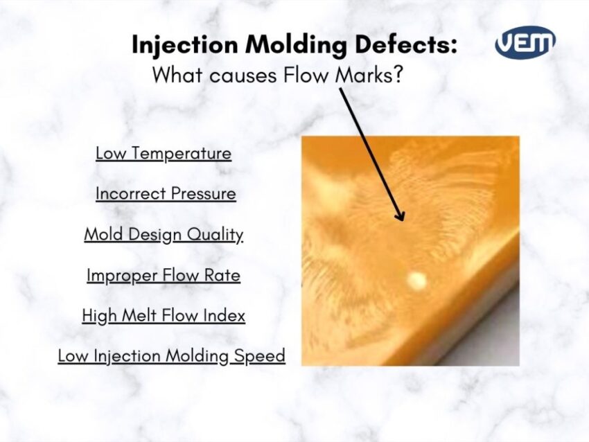
Flow marks in Injection Molding can be caused due to various reasons! It could be due to machine settings, material reasons, or due to the construction of the mold. Although there are various reasons, it is generally caused due to the uneven cooling of the plastic or simply, plastic cooling at different rates. In this section, we take a look at some of the most common causes that lead to non-uniform cooling of the plastic and the formation of flow marks in injection molding.
The primary goal of heating the plastic is to enable it to distort so that it can flow easily. The temperature of the melted plastic determines the viscosity of the melt.
MFI, abbreviated as The Melt Flow Index, is a major factor that contributes to the formation of flow marks in injection molding. MFI is basically a measure of the ease of flow of the melted plastic and is closely tied to the temperature. It basically indicates the flow characteristics of melted plastic.
The formation of flow marks is inversely proportional to the MFI. The higher the MFI, the lower the chances of the formation of the defect! Consequently, thermoplastics that have a low MFI are more prone to flow marks. You should note that if the temperature of the plastic is too hot, then it will start to degrade, but if the temperature is too low, then the flow marks will start to form. Thus, it is crucial to track the temperature of the plastic through the injection molding machine. It is also crucial to monitor the temperature when it is being injected.
If the temperature of the mold is not optimum, it can cause the formation of flow marks. When the mold temperature is too low, the surface layer solidifies rather quickly, which makes it difficult to establish a jet flow and this can cause flow marks in a part. Flow marks can also occur when the surface layer hardens faster than the resin is being filled in the mold.
Sometimes, the molds are pre-chilled and they are not heated, because the part cools in the mold but if the temperature of the mold is too low, then the melt may also cool quickly after it enters the mold. Flow markings appear when the mold areas cool earlier around the gate and the hotter fluid flows over the cooled melt.
A low injection speed could be one of the factors that can lead to the formation of flow marks. It is crucial that the melted plastic reaches the mold in a timely manner before it loses its stored heat. Thus, the injection speed i.e. the rate at which the melt is injected should be optimum.
It is also crucial that the injection speed should be consistent when the plastic enters the mold! If the flow rate isn’t consistent, then the melt will slow down, cool inconsistently, drop in temperature before molding, and lead to the formation of flow marks.
The rate of melting plastic is directly proportional to the injection pressure. You should note that
homogeneity during melting is because of compaction and if there isn’t enough pressure, the compaction won’t be enough. Thus, a low injection pressure will lead to the formation of flow marks.
The melting process in the mold is often slowed when the flow is restricted especially when the runner and gates are too thin! This causes certain portions of the melt to lose their temperature, ultimately leading to the formation of flow marks.
There are various parameters of the injection molding machine that can lead to the formation of flow marks. It is important that these machine settings are optimized! Let’s take a look at some instances:
The next reason for the formation of flow marks can be attributed to poor mold designs! Let’s take a look at some of the examples and instances of poor mold design:
If adequate measures are taken, flow marks can be avoided in injection molding! Flow marks troubleshooting in injection molding requires a thought-out mold design and fine-tuning.
In this section, we enlist some of the parameters that should be monitored for and adjusted to avoid the formation of flow marks in parts. Let’s understand these strategies and the best ways to minimize flow marks in injection molding:
Pressure parameters play an important role in preventing various injection molding defects, including flow marks. Defects such as flow marks can be prevented by increasing the back and holding pressure of the injection molding machine. It is critical to find a balance with other parameters as excessive injection pressure can also lead to the formation of other types of defects.
Back pressure helps to enhance compaction by pushing the fluid through the runners and the mold. You can also consider increasing the holding pressure as this helps to improve the surface quality.
Temperature has a significant impact on the formation of flow marks in injection molding. You should note that when it comes to temperature parameters, both the machine and the mold are sources of heat! Any changes in temperature to either the mold or the machine can introduce defects in the parts. Let’s understand some of the parameters that can help you prevent flow marks in injection molding:
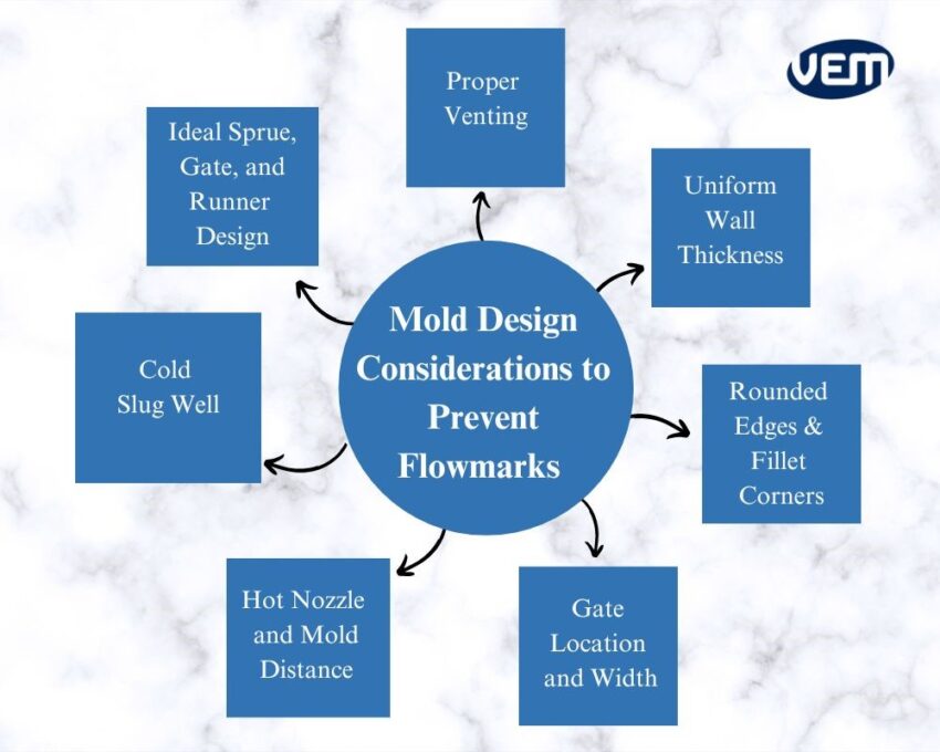
If the design of the gate, sprue, and runner is not optimal, then the material flow will be restricted. Thus, it is deciding to incorporate the correct design of the sprue, gate, and runners in the mold. Today, simulation tools such as Moldflow can help you identify the ideal gate, sprue, and runner sizes for your mold.
It is also influential to have proper venting in the mold as it enables any trapped air in the mold cavity to escape once the molten resin enters the mold.
The vent depth is dependent upon the plastic viscosity but the thumb rule is, that the stiffer the materials are, the deeper the vents need to be. You should consider placing vents at the end of each runner section and opposite the gate.
The wall thickness of the mold has a significant impact on the cooling of the melt. The molds that have a uniform wall thickness enable the melt to cool well but if the mold has a variable wall thickness, then the cooling will be uneven. As a thumb rule, the wall thickness should transform smoothly across the mold. In addition, the thicker areas of the mold can contain more fillets and rounded corners to facilitate uniform cooling.
Sharp edges in the mold design often cause uneven flow patterns which ultimately lead to the formation of flow marks. It is recommended to round the edge of the corners or implement fillet edges in the design for better material flow. This reduces the impact of the flow direction change and avoids unbalanced flow patterns. Implementing fillet corners and rounded edges also helps with mold release.
The key is to implement the correct width of gates and runners at the correct positions. If the diameters of the gates and runners are too small, then the flow of the melt will be restricted. The smaller the channel, the quicker the melt will cool and this premature cooling prevents a sufficient amount of melt from entering the mold.
In addition, there are some guidelines that can be followed to position the gates. For instance: In the case of gears, the gate should be positioned at the gear center for maximum efficiency. When the guidelines are not specified, the gate should be typically placed on the thinnest wall of the mold. This placement reduces the temperature transfer and thus, the mold’s flow patterns won’t be disturbed!
If the melt has a longer distance to travel, it is likely to cool faster thus, you can consider reducing the distance between the hot nozzle and the mold to avoid uneven cooling and the formation of flow marks. You must note that the melt should be hot enough to flow freely in the mold but not so hot that it solidifies. If the distance cannot be reduced, you can consider employing a hot runner to keep the melt hot.
A cold slug well is a small solid plastic nub that cools and solidifies inside the nozzle tip during the cooling phases of an injection molding cycle. It is an important part of the plastic mold design and is implemented to store cold slug that is caused due to heat loss and low temperature by the nozzle.
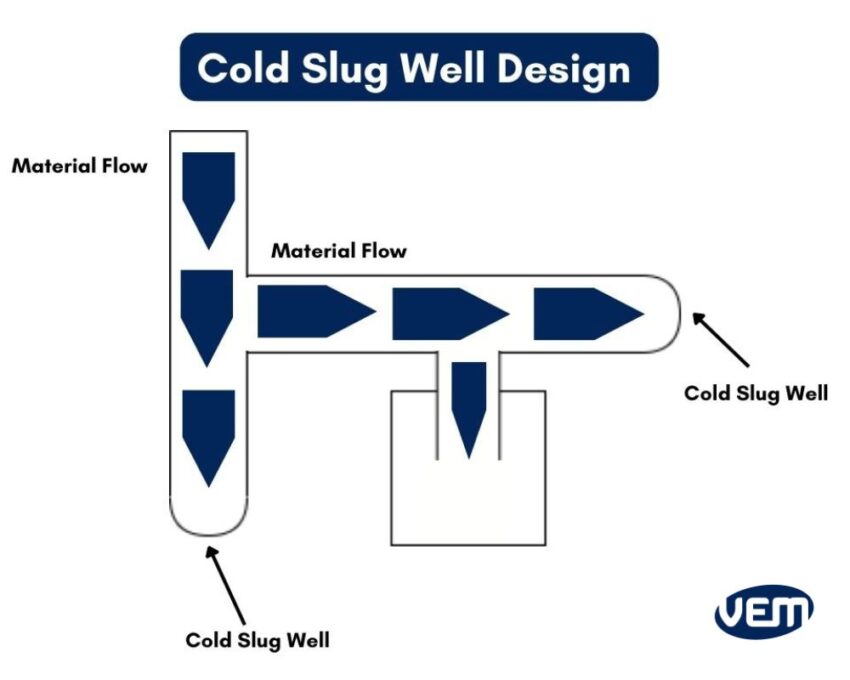
Cold slugs if not collected in the well, result in poor material flow and can even lead to complete blockages, thereby causing a variety of defects, including flow-marks!
The injection speed is directly proportional to the injection pressure. The higher the injection pressure, the faster the flow rate of the material. You should note that applying more than required and too much injection pressure can cause another defect known as jetting.
If the injection speed is low, then the melt has more time to cool thus, increasing the chances of flow line formations in the part.
The next factor for reducing any type of defect in injection molding is educating the operators. They should be updated with the operating procedures and trained with respect to engineering plastic materials.
It is crucial that the operators on the shop floor understand various aspects such as the correct automatic cycling of the injection molding machine and the proper application of the mold lubricant.
There are various reasons that lead to the formation of flow marks in a molded part and it takes knowledge and expertise to avoid the same! An injection molder needs to also ensure that other defects are also being avoided with flow marks.
The team at VEM Tooling has the experience to help you understand these technicalities! Our proactive approach aims to reduce the occurrence of injection molding defects. Contact VEM Tooling to understand how to achieve a seamless manufacturing process and reduce the risk of defects.